

1:Introduce Signal pressure
The input signal pressure of the transmitter is generally introduced in three ways: ①through the straight-through terminal joint; ②through the waist flange; ③through the valve group.
1) Via feed-through terminal fittings
Figure 5.1 shows the structure of the straight-through terminal connector.There is an external thread on the connector body 1, which is screwed to the pressure guide port of the transmitter.Threads are available in various specifications to suit the needs of different types of transmitters.The nozzle 5 is welded with the pressure guiding conduit, and it also has various specifications to match the pressure guiding conduits of different diameters and wall thicknesses.When disassembling, as long as the outer nut 4 is unscrewed, the transmitter and the pressure guiding pipe can be separated.
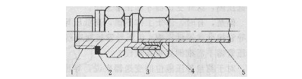
1-joint body; 2-washer; 3-ferrule; 4-jacket nut; 5-connector
2:Through the waist flange
A waist flange is a small flange, shaped like a waist, sometimes called an oval flange.It is fixed on the 6yvpressure guide port of the transmitter with two screws. One end of the flange is connected with the transmitter, and the other end has an internal thread interface. The straight-through terminal joint or the pressure guide pipe is screwed on this interface.When disassembling, unscrew the two fixing screws of the waist flange, or unscrew the outer nut of the straight-through terminal joint, the pressure guiding tube and the transmitter can be separated.
3:connected by valve
Transmitter valve group has three valve group, two valve group, five valve group and so on. Figure 5.2 is the outline drawing of the 3051S transmitter. The introduction of the input pressure of the transmitter adopts a three-valve group.
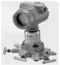
5.2
①Three valve group
The connection between the differential pressure transmitter and the pressure guiding pipe can also be through the three-valve manifold.
Figure 5.3(a) is the working principle diagram of the integrated three-valve group, which consists of two pressure-inducing valves 1 and a balance valve 2. The integrated three-valve manifold is more compact and easier to install than the separate three-valve.
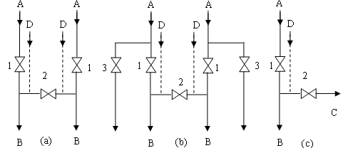
Figure 5.3 The working principle of the instrument valve group
(a) three-valve group; (b) five-valve group; (c) two-valve group A-connected to process pressure; B-connected to transmitter pressure port; C-purging port (drainage port); D-connected to test pressure; 1-pressure valve; 2-balance valve; 3-sewage valve
The inlet A of the three-valve group is directly connected to the terminal joint. The impulse conduit is welded to the nozzle of the terminal joint.Outlet B is fixed to the pilot pressure port of the transmitter with 4 screws and washers.The two outlets B of the three-valve group, that is, the distance between the two pressure guiding ports of the transmitter, are generally 54mm.
When the high and low pressure valves of the three-valve group are closed and the balance valve is opened, the pressures of the high and low pressure measurement chambers of the transmitter are balanced, and the differential pressure is O.When the high and low pressure valves are opened at the same time and the balance valve is closed, the pressures at the two output ends are the high pressure and low pressure of the throttling device respectively;When the balance valve is opened, one of the high and low pressure valves is closed, and the other valve is open, then the pressures at both output ends are high or low pressure.
There are also two pressure check ports D on some three-valve groups, which are blocked with plugs during normal operation.When calibrating, first cut off the high and low pressure valve and balance valve, and then pass the calibrated pressure from the test port, so that the transmitter can be calibrated without disassembling other joints.
②Five valve group
The five-valve group is based on the three-valve group with two additional blowdown valves 3 (empty), and its working principle is shown in Figure 3.5(b).During normal operation, close the two groups of blowdown valves and balance valves;When the instrument is at the zero position, cut off the high and low pressure valves and open the balance valve.Some five-valve groups also have two pressure calibration ports D. To calibrate the instrument, just open the test port and connect the calibrated pressure.Therefore, inspection, verification, sewage discharge and flushing can be carried out on these five valve groups, which is more flexible and much easier to install.
③Two valve groups
Two valve groups are generally used for pressure transmitters, through which the process pressure is connected to the pressure guide port of the transmitter, and its working principle is shown in Figure 5.3(c).Among them, A is connected to the process conduit, B is connected to the pressure guide port of the pressure transmitter, C is used for blowdown or purging, and D is the calibration port. Two-valve manifolds can sometimes also be used with differential pressure transmitters.
2. Forward and reverse conversion
When using the differential pressure transmitter to measure the liquid level of the container, the high pressure side is connected to the pressure guiding pipe at the bottom of the container, and the low pressure side is connected to the pressure guiding pipe at the upper part of the container, so that the output of the instrument can follow the custom, the liquid level rises, and the output increases; the liquid level down, the output decreases.Similarly, when measuring fluid flow with a differential pressure transmitter and a throttling device, the positive pressure conduit is connected to the high pressure side of the transmitter, and the negative pressure conduit is connected to the low pressure side of the transmitter, so that the transmitter can work normally.
However, sometimes due to careless work, the high and low pressure conduits are laid in reverse, or for the convenience of maintenance and operation, the positive pressure conduit must be connected to the low pressure side of the transmitter, and the negative pressure conduit must be connected to the high pressure side of the transmitter.In this case, can the transmitter still work normally? Does the pressure guiding pipe need to be removed and re-laid?
For the transmitter that measures the static pressure level, if the pressure guiding pipe is reversed, it can only violate the routine and make the output reverse indication.When the liquid level is the lowest, the output is not zero, but 100%; when the liquid level is the highest, the output is not the maximum, but 0%. In the early years, the differential pressure gauge without zero migration was used in this way.However, for the differential pressure transmitter that measures the flow, the pressure guiding pipe is reversed, and it generally cannot work.
The smart transmitter uses the configuration of the hand-held communicator to realize its function. There is a forward and reverse conversion module inside the transmitter. As long as it is set to the reverse direction, the problem of reverse connection of the pressure guiding pipe can be solved. .For non-smart transmitters, some circuit boards also have a forward and reverse plug, as long as the plug position of the plug is changed, the forward and reverse conversion can also be realized.
For non-smart transmitters, some circuit boards also have a forward and reverse plug, as long as the plug position of the plug is changed, the forward and reverse conversion can also be realized.
For any transmitter with forward and reverse conversion, if the pressure guiding pipe is reversed, as long as it is changed to the reverse output state, plus a certain zero point positive and negative migration, the transmitter can work in the normal output direction. , without the need to modify the pressure catheter.
Post time: May-10-2022