

Today we take the orifice plate differential pressure transmitter as an example to illustrate the installation position when they measure gas, liquid and steam.
(1) Measure liquid medium
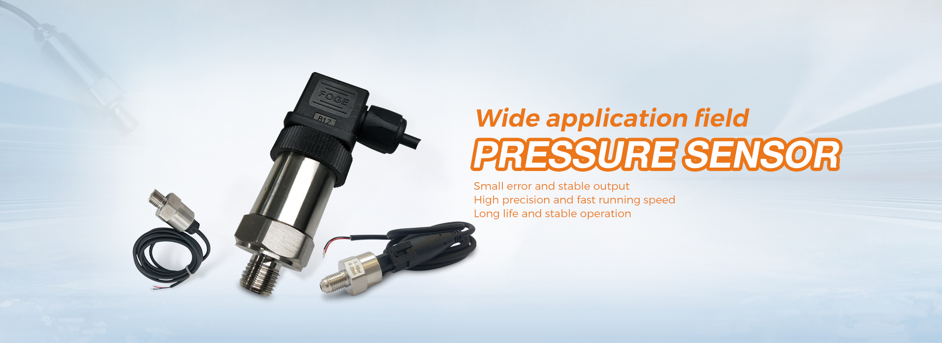
When the transmitter measures the pressure or differential pressure of the liquid, it is mainly to prevent the liquid entering the conduit from mixing with gas and accumulating in the pressure guiding pipe, so that the static pressure head changes.For this purpose, the transmitter should be installed at or below the level of the pressure measuring point, as shown in Figure 5.4(a).If the transmitter has to be installed above the pressure measuring point, move the pressure guiding tube down a distance from the pressure measuring point and then upward to form a U-shaped tube, so that the gas in the liquid can be released as soon as possible.At the top of the conduit, a gas collector or a vent valve should be installed, as shown in Figure 5.4(b).Whether it is above or below, if there is sediment in the liquid, in order not to block the conduit, a settler is required.If the liquid to be tested is corrosive or viscous, an isolator should be installed, and the installation position is shown in Figure 5.4(c).
(a)Transmitter under throttling (b)Transmitter above throttling (c)Transmitter Installation Using Isolators
1– throttling device; 2 –a isolator; 3– a differential pressure transmitter
5.4 Measuring gas installation
(2) Measuring gas medium
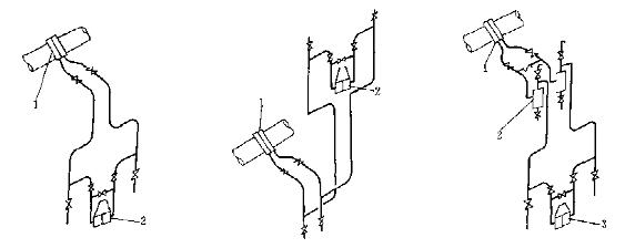
When the transmitter measures the differential pressure or pressure of the gas, it is mainly to prevent the liquid and dust from entering the pressure guiding pipe, so that the static pressure head changes and the measurement error increases. For this reason, the transmitter should be installed above the pressure measuring point.If it has to be installed below, it is necessary to install a settler or settling pipe at the lowest point of the pressure guiding pipeline to separate out condensate and dust. If measuring corrosive gases, an isolator should also be installed.Figure 5.5 shows the measurement gas installation location.
(a)Transmitter above throttling (b)Transmitter under throttling
1–throttling device; 2–a isolator;
Figure 5.5 Installation position of measuring gas
(3) Measuring steam medium
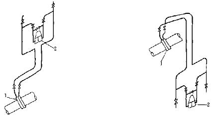
When the transmitter measures steam, the steam enters the transmitter measurement chamber in the state of condensate.If you do not carelessly and allow steam to enter the transmitter, it will damage the detection components of the instrument.For this purpose, two equalizers should be installed on the differential pressure connection line near the throttling device.There should be condensed liquid in the balancer, and ensure that the liquid level in the two balancers is equal.Because the steam is measured in a liquid state, the transmitter should be installed below; if it has to be installed above, a gas collector or vent valve should be installed.The installation position of the measurement steam medium is shown in Figures 5.6(a) and 5.6(b).
(a)Transmitter under throttling (b)Transmitter above throttling
1–throttling device; 2–a balancer; 3–a transmitter
Figure 5.6 Measuring the installation position of the steam medium
(4) Installation of measuring liquid level
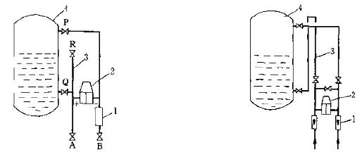
(a)Transmitter under throttling (b)Transmitter above throttling
1– throttling device; 2– a balancer; 3– transmitter
Figure 5.7 Installation position of measuring liquid level
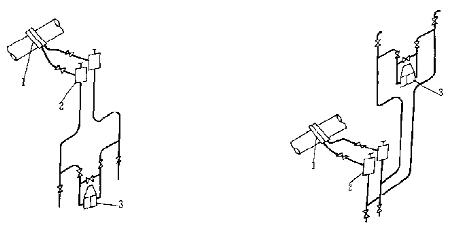
According to the principle of static pressure, when using differential pressure or pressure transmitter to measure the liquid level or boundary level of the liquid in the container, there can be various installation methods according to the properties of the measured medium and the pressure in the container. Figure 5.7 shows two of them.
Figure 5.7(a) is to measure the liquid level of the closed container, the negative pressure pipe is dry gas, and the positive pressure pipe is the liquid to be measured.In order to prevent the precipitation of condensate in the negative pressure pipe and increase the static head of the negative pressure, a condensing tank 1 is installed below it.The calibration tube 3 is used to verify the range of the transmitter, and its height is exactly equal to the highest liquid level in the container.In this way, as long as the valve Q is closed, the valve R is opened, and then the measured medium is poured from the valve R. When the outlet of the valve R begins to overflow, the full-scale pressure is passed to the transmitter.
If the meter output is not full scale at this time, the range screw can be adjusted.If the measured medium is corrosive and cannot be obtained temporarily, it can be calibrated with water or other medium, and then according to the density of water or other medium and the density of the measured medium, the calculated value is calculated, and then based on the actual indication value and the calculated indication value The difference is used for range adjustment.
Figure 5.7(b) is a schematic diagram of the liquid level measurement of flushing liquid and isolating elbows.In order to prevent the measured medium from entering the instrument and affecting the measurement, the flushing liquid is injected from the positive pressure conduit, and the gas is injected into the negative pressure conduit.The purpose of blowing gas is to save flushing fluid.In order to prevent the measured heavy medium from entering the pressure guiding pipe and the instrument body when the flushing liquid stops playing, an isolation elbow is added to the positive pressure pipe, and its height should be higher than the highest liquid level, so that the measured medium will be The flushing fluid is separated and it is impossible to enter the measuring chamber of the instrument.
Post time: May-16-2022