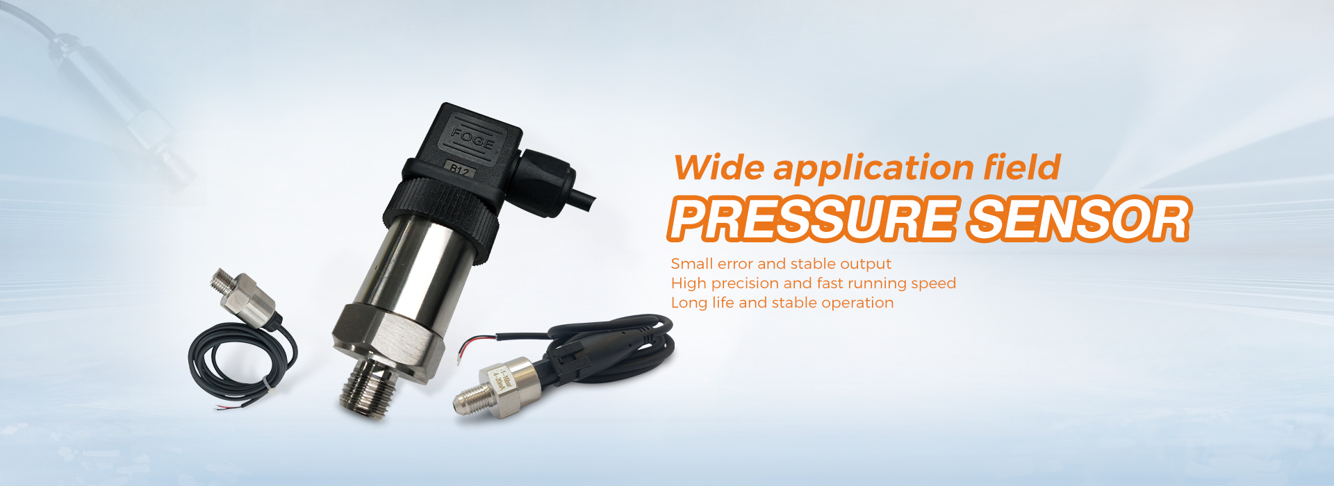
Many pressure sensors use microelectromechanical systems (MEMS) technology, which consists of four varistors connected using a Wheatstone bridge structure. When there is no pressure on these sensors, all resistance values in the bridge are equal. When an external force is applied to the bridge, the resistance values of the two opposing resistors will increase, while the resistance values of the other two resistors will decrease, and the increased and decreased resistance values are equal to each other.
Unfortunately, things are not that simple because the sensors have offset and gain errors. Offset error refers to the presence of output when no pressure is applied to the sensor; Gain error refers to the sensitivity of the sensor output to external forces applied to the sensor.Typical sensors typically have an excitation voltage of 5V and a nominal full-scale output of 2mV/V. This means that when the excitation voltage is 5V, the nominal full-scale output is 2mV/V × 5V=10mV, and the offset voltage may be 0.2mV, or 2% of the full-scale; The minimum and maximum full-scale output voltages may be 5mV and 15mV, or ± 50% of the nominal full-scale.
Assuming two resistors are connected in series to form a resistor string, since they are equivalent resistors, the node voltage between the two resistors is half of the voltage of the resistor string. If one resistor increases by 1% and the other resistor decreases by 1%, the voltage at the two resistor nodes will change by 1%. If two resistors are connected in series in parallel, as shown in Figure 1, the resistance values of the lower left resistor and the upper right resistor both decrease by 1%, and the other two resistors increase by 1%, then the voltage between the two “middle” points will change from zero difference to 2%. The configuration of two parallel branches is called a Wheatstone bridge.
If we do not understand the true relationship between offset and sensor output voltage and pressure, we can only roughly estimate the magnitude of pressure applied to the pressure sensor. This means that sampling calibration methods are needed to achieve better accuracy. Fortunately, the offset and full-scale error of a given pressure sensor are quite stable over time, so once the pressure sensor is calibrated, it may not be necessary to change the calibration coefficient during its lifetime to meet the accuracy requirements. Of course, the system usually needs to be recalibrated every time it is powered on.
The basic signal conditioning circuit consists of an instrumentation amplifier and an analog-to-digital converter (ADC). The instrument amplifier amplifies the small output voltage from the sensor to a level suitable for the ADC, and then the ADC converts the amplified sensor output voltage into digital form, which is then handed over to the controller or DSP for processing. Instrumentation amplifiers can be used to avoid bridge overload, which can alter the sensor output voltage value.
The full-scale output of the sensor is the maximum input, which can be seen at the amplifier input. When the sensor output is at full scale, the ADC input should be close to its full scale value, which is usually the reference voltage VREF of the ADC.
Post time: Apr-27-2025


